prototol_gre
Overview
passenger protocol(inner)
The type of protocol (IPv4, IPv6, or MPLS) used by the networks that are connected by a GRE tunnel. Packets that are encapsulated and routed across the transport network are payload packets.encapsulation protocol(gre)
The type of network layer protocol (GRE) used to encapsulate passenger protocol packets so that the resulting GRE packets can be carried over the transport protocol network as the packet payload.transport protocol(outer)
The type of protocol (IPv4) used by the network that routes passenger protocol packets through a GRE tunnel. The transport protocol is also called the delivery protocol.
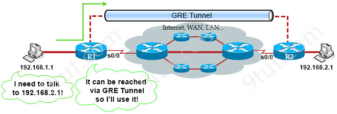
Generic Routing Encapsulation (GRE) is one of the available tunneling mechanisms which uses IP as the transport protocol and can be used for carrying many different passenger protocols. The tunnels behave as virtual point-to-point links that have two endpoints identified by the tunnel source and tunnel destination addresses at each endpoint.
A GRE packet header structure is represented in the diagram below.

Five GRE flag bits indicate whether a particular GRE header includes any optional fields (Checksum, Offset, Key, Sequence Number, and Routing). Of the five optional fields, filter-based GRE IPv4 tunneling uses the Key field only.
The first two octets encode GRE flags, indicate whether a particular GRE header includes any optional fields (Checksum, Offset, Key, Sequence Number, and Routing)
The 2-octet Protocol Type field contains the value 0x0800 to specify the EtherType value for the IPv4 protocol.
The 4-octet Key field is included only if the Key Present bit is set to 1. The Key field carries the key value of the tunnel defined on the encapsulator. If the GRE tunnel definition specifies a key, the Packet Forwarding Engine for the encapsulating endpoint sets the Key Present bit and adds the Key to the GRE header.
How GRE works
Topopogy

1 | R1 (GRE config only) |
1 | R2 (GRE config only) |
Sssigns the IP address for the tunnel interface: 10.0.0.1/24.
The IP addresses of two tunnel interfaces must be in the same subnet
(10.0.0.1/24 on R1 & 10.0.0.2/24 on R2 in this case).
This address is not used by Delivery header who uses tunnel source and tunnel destination(tunnel source and tunnel destination should reach each other!!!)
Flow
When the sending router decides to send a packet into the GRE Tunnel, it will “wrap” the whole packet into another IP packet with two headers: one is the GRE header (4 bytes) which uses to manage the tunnel itself. The other is called “Delivery header” (20 bytes) which includes the new source and destination IP addresses of two virtual interfaces of the tunnel (called tunnel interfaces). This process is called encapsulation.

In the example above when R1 receives an IP packet, it wraps the whole packet with a GRE header and a delivery header. The delivery header includes new source IP address of 63.1.27.2 (the IP address of R1’s physical interface which is used to create tunnel) and new destination IP address of 85.5.24.10 (the IP address of R2’s physical interface which is used to create tunnel).
It is important to note that the GRE tunnel does not encrypt the packet, only encapsulate it. If we want to encrypt the packet inside GRE Tunnel we must use IPSec.
When the GRE packet arrives at the other end of the tunnel (R2 in this case), the receiving router R2 needs to remove the GRE header and delivery header to get the original packet.